When a 100 MW industrial boiler burns coal, the flue gas leaving the furnace carries more than carbon dioxide and water vapor. At the boiler outlet, sulfur dioxide can exceed several thousand mg/Nm3, nitrogen oxides are present in the hundreds of mg/Nm3 range, and the gas also contains ash, chlorides, and trace metals. Flue gas treatment is the combination of physical and chemical processes that removes those contaminants before the gas reaches the stack. It is not a single piece of equipment; it is a system with several stages, each chosen around the fuel, the process, and the emission limit.
What Is Flue Gas Treatment?
Flue gas treatment refers to the physical and chemical processes applied to exhaust gas from combustion sources. The gas is first characterized by its temperature, moisture load, oxygen content, particulate level, and chemical makeup. Then a treatment train is built to meet a defined outlet specification.
Most industrial flue gas treatment trains deal with five groups of pollutants:
- Particulate matter: fly ash, soot, and condensed salts.
- Acid gases: sulfur dioxide (SO2), hydrogen chloride (HCl), and hydrogen fluoride (HF).
- Nitrogen oxides: nitric oxide (NO) and nitrogen dioxide (NO2), often grouped as NOx.
- Heavy metals: mercury, arsenic, and selenium compounds.
- Organic pollutants: dioxins, furans, and volatile organic compounds.
Some pollutants are removed by separation, for example electrostatic precipitation. Others are converted, for example NOx is reduced to nitrogen and water. In a well-designed plant, these mechanisms operate in series rather than in isolation.
Main Flue Gas Treatment Technologies
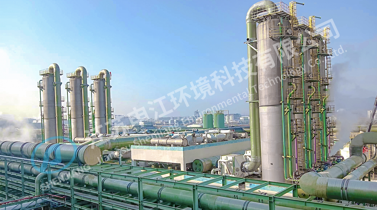
No single technology can handle all flue gas pollutants. A complete system usually combines a desulfurization stage, a NOx conversion stage, and a particulate or aerosol polishing stage. That is why the treatment train is designed as a whole, not as independent boxes.
Wet Flue Gas Desulfurization
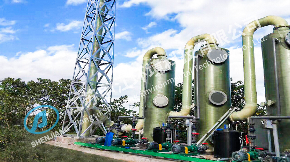
Wet flue gas desulfurization is the most widely used method for SO2 control. The gas is brought into contact with a limestone or lime slurry in an absorber tower. Sulfur dioxide dissolves and reacts with the alkaline reagent to form calcium sulfite or sulfate. Removal efficiency is typically 90 to 98 percent and can be higher with additives and a carefully sized absorber. The gas leaving the absorber is saturated with water vapor, so the downstream ducting, reheating system, or wet stack must be designed to handle condensation and acidic droplets.
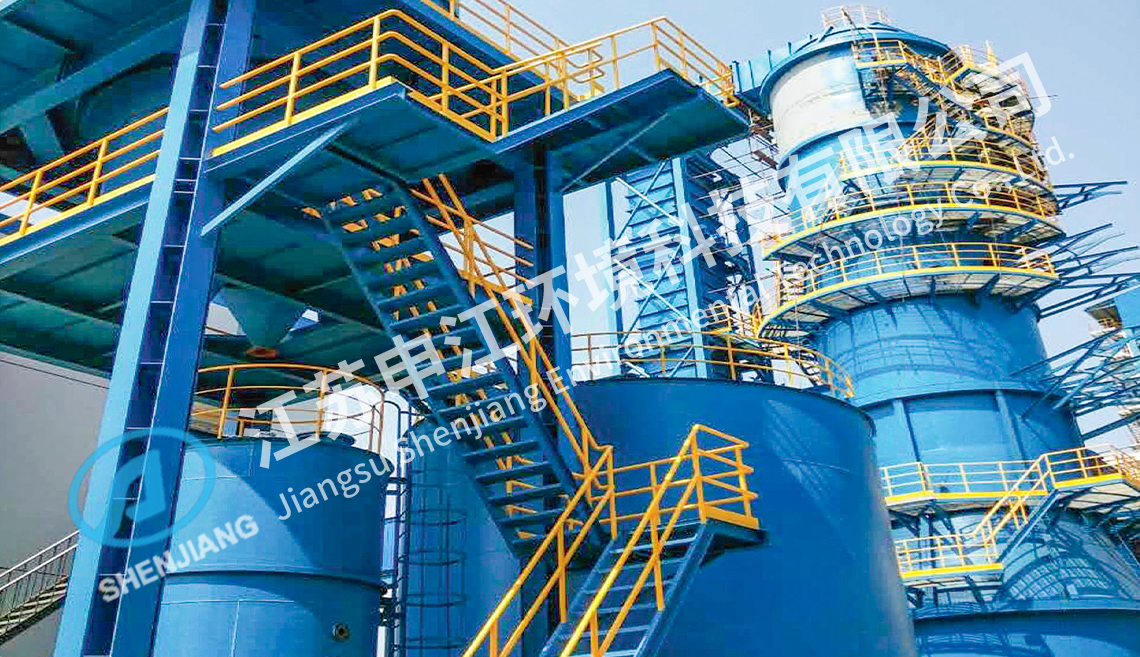 SNCR Flue Gas Denitration System for Coal-Fired BoilersDesigned for coal-fired boilers, this SNCR system injects ammonia or urea in the furnace at 850–1100°C to cut NOx without a catalyst, complementing downstream SCR.View Product →
Selective Catalytic Reduction
Selective catalytic reduction controls NOx by injecting ammonia or urea into the flue gas and passing it over a catalyst. The reaction converts NOx to nitrogen and water. A typical SCR system operates between 300 and 400 °C and removes 70 to 90 percent of the NOx. The catalyst is sensitive to poisoning by sulfur compounds, arsenic, and fine ash, so its position in the flue gas stream affects catalyst life and maintenance cost.
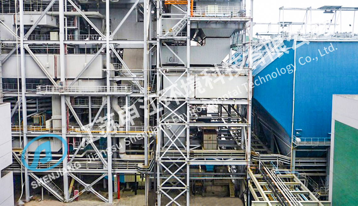 SCR Denitration System with Catalyst for NOx ControlOperating at 300–400°C, this SCR system achieves 70–90% NOx removal with ammonia and a catalyst. Its sensitivity to sulfur and arsenic makes proper flue gas placement essential.View Product →
Particulate and Aerosol Control
Before or after the absorption stages, particulate matter is removed with cyclones, bag filters, electrostatic precipitators, or wet scrubbers. For fine droplets, submicron particles, sulfuric acid mist, and condensed metals, a wet electrostatic precipitator is often used. It applies a high-voltage field to charge particles and collects them on wetted surfaces, which also prevents re-entrainment. This helps the plant meet opacity limits and removes aerosols that can pass through an absorber.
 Wet Electrostatic Precipitator for Fine Mist and Particle ControlFor fine droplets and aerosols that pass an absorber, this wet ESP applies a high-voltage field and wetted collection surfaces to capture submicron particles, acid mist, and condensed metals, preventing re-entrainment and opacity violations.View Product →
Table 1. Typical performance ranges for common flue gas treatment stages.
| Stage |
Primary target |
Typical removal |
Key design factor |
| Wet flue gas desulfurization |
SO2 and HCl |
90-98% |
Absorber liquid-to-gas ratio |
| Selective catalytic reduction |
NOx |
70-90% |
Catalyst temperature and activity |
| Dry sorbent injection |
Acid gases |
50-90% |
Temperature and contact time |
| ESP or baghouse |
Fly ash |
95-99.9% |
Collection area or filter velocity |
| Wet electrostatic precipitator |
Fine particles and acid mist |
80-95% |
Saturation and water quality |
| Activated carbon injection |
Mercury |
60-95% |
Carbon dose and contact time |
How to Choose a Flue Gas Treatment System
Start with the emission limit and work backward. A removal efficiency number is meaningless without a defined inlet concentration, gas flow rate, temperature, and time profile. The same SO2 concentration can require different absorber designs if the dust load is high or the gas temperature varies.
The main criteria are:
- Define the actual pollutant profile with fuel analysis and stack test data; avoid relying only on nameplate values.
- Set the target emission limit based on current permit conditions and likely future limits.
- Evaluate temperature and moisture at every point: condensation can cause corrosion and false readings.
- Choose the process whose byproduct can be handled on site, whether it is gypsum, wastewater, salts, or collected fly ash.
- Compare auxiliary power consumption, reagent consumption, water consumption, and maintenance access.
- Confirm the vendor can provide the complete train, including ductwork, supports, platforms, controls, and commissioning.
The pressure drop of each stage also matters. In a retrofit, the available fan capacity often limits what can be added. A higher-efficiency scrubber is useless if the existing induced draft fan cannot carry the extra pressure loss.
Utility and industrial power projects have demonstrated that interface problems, rather than individual component failures, cause the longest delays. For that reason, it helps to review field experience from the power industry as a practical reference when planning a flue gas treatment upgrade.
Materials of Construction and Corrosion Control
Flue gas treatment equipment operates in one of the most corrosive environments found in an industrial plant. After the absorber, the gas is saturated with water vapor and contains residual sulfurous acid, chlorides, and fluorides. The acid dew point can be reached quickly when wall temperatures drop, leading to severe local corrosion.
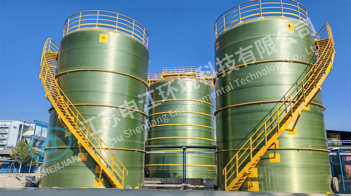
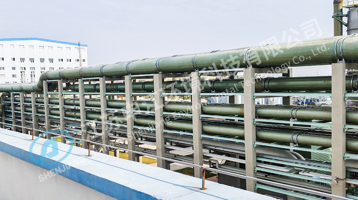
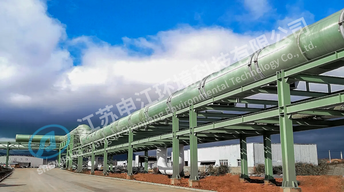
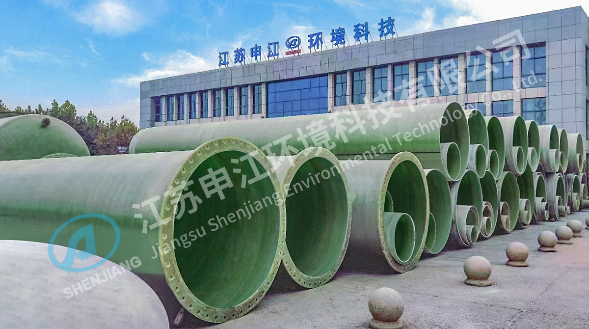
For scrubber vessels, absorber towers, ducting, and piping, fiberglass reinforced plastic (FRP) is a common construction material because it resists a broad range of chemicals and does not depend on coatings that can fail over time. FRP is also lighter than carbon steel, which simplifies supports and foundations. Temperature is the main limitation: most FRP systems are designed for continuous service below 100-120 °C unless the resin system is selected for higher duty. In processes with hot inlet gas, a quench section is used to cool the gas before it enters the FRP absorber.
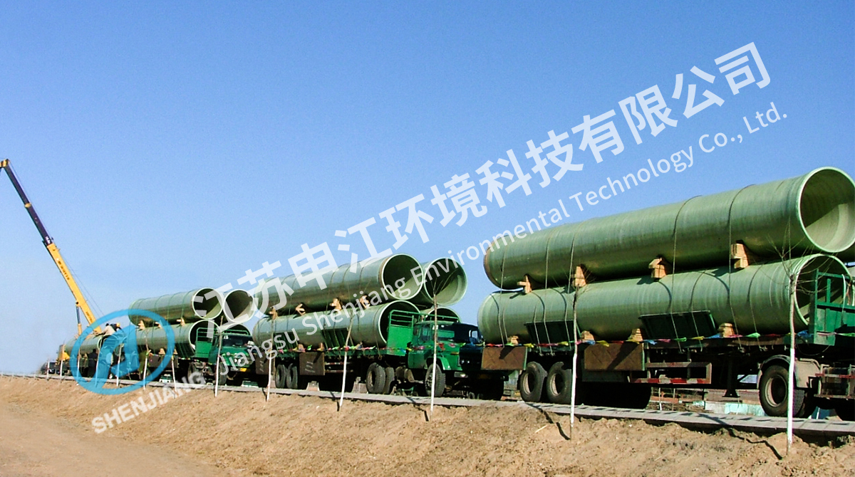
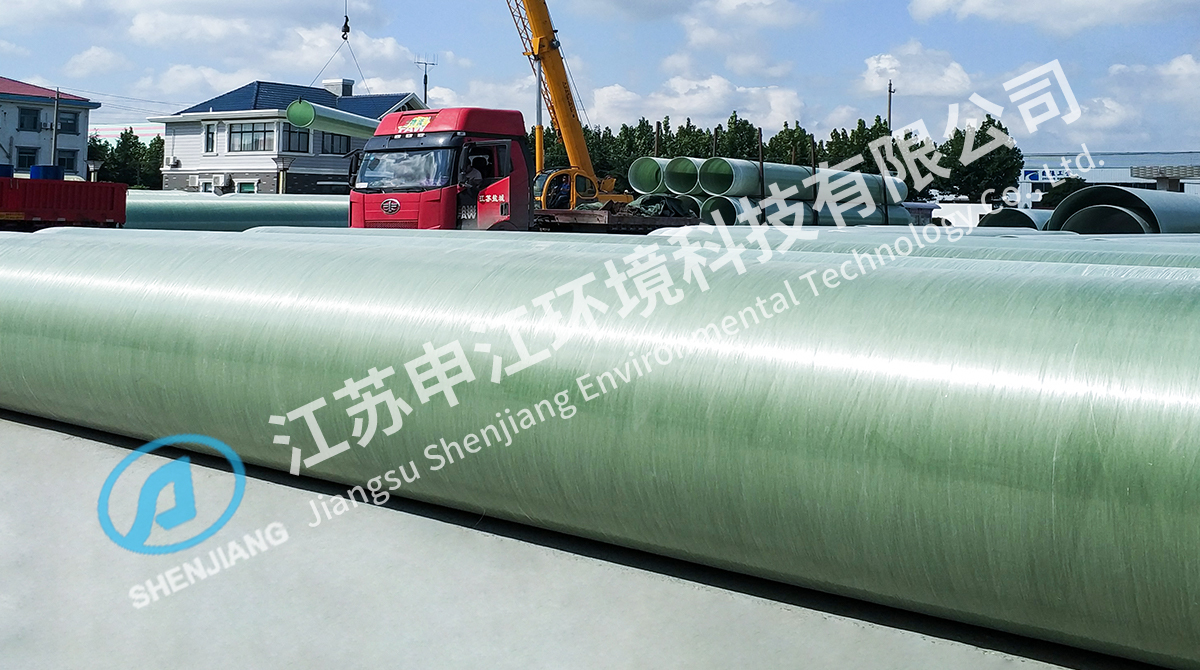
FRP components also need proper handling. If pipes and towers are stored in direct sunlight or with poor support, the outer surface can degrade or the shape can distort before the system is installed. Storage precautions for desulfurization pipelines are part of the asset life, not an afterthought.
Why the Right Package Matters
Flue gas treatment is not a commodity purchase. The system must handle load changes, variation in fuel quality, and upset events without tripping the boiler or missing the emission limit. A packaged design from one supplier reduces the risk of mismatched components, undefined interfaces, and unclear responsibility during commissioning.
In practice, a flue gas treatment project succeeds when the buyer specifies the gas composition, operating flexibility, and material requirements clearly, and the supplier matches the process train to those boundaries. That combination is what turns a line on a flow diagram into a plant that runs reliably.




 English
  中文简体
中文简体 Español
 عربى
عربى русский
 ไทย
ไทย Indonesia
 Tiếng Việt