A 300 t/h coal-fired boiler at a paper mill moves roughly 400,000 m³/h of flue gas at 130 °C, carrying 1,800 mg/Nm³ of SO2 into the absorber, while the local emission limit sits at 35 mg/Nm³. Four numbers decide both the price and the performance guarantee long before a single drawing is issued: gas flow, inlet SO2 concentration, absorber inlet temperature, and the reagent the site can realistically store and handle. Tower diameter, pump count, oxidation air duty and dewatering capacity all follow from those four.
That is why gas desulfurization equipment should be treated as a system sized from the gas rather than a product picked from a catalogue. What follows is how the main process routes differ, which design margins are worth writing into a contract, and where the corrosion-resistant parts of the train are most often under-specified.
What Gas Desulfurization Equipment Actually Covers
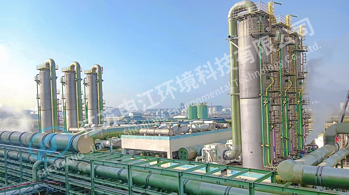
A wet FGD quotation that lists only "the absorption tower" is missing roughly half the scope. A complete train normally includes:
- Absorber tower with spray levels, mist eliminator and oxidation zone
- Recycle pumps, one duty pump per spray level plus standby
- Oxidation air blowers and spargers
- Limestone preparation: silo, ball or wet mill, slurry tanks and agitators
- Gypsum dewatering: hydrocyclones plus vacuum belt filters or centrifuges
- Flue gas ducting, booster fan, dampers and expansion joints
- Bleed wastewater treatment and a CEMS with the required averaging period
Items dropped in the early commercial stage tend to return later as change orders: the bypass damper, the slurry bleed line, and the duct run between the absorber outlet and the stack. Ask for a battery limit drawing with the first quotation, not after the order.
Match the Process Route to the Flue Gas
Wet limestone-gypsum remains the default above roughly 100 t/h of coal firing: cheap reagent, 95–99% removal and a gypsum byproduct with a real market. Semi-dry circulating fluidised bed or spray dryer routes suit smaller units, low-sulfur coals, or brownfield sites where a wet plume and a liquid effluent are not acceptable. Seawater scrubbing only makes sense where a coastal plant already moves large cooling water flows and the discharge alkalinity can be recovered. Ammonia-based routes pay off where a fertilizer or chemical complex can absorb the ammonium sulfate output.
Table 1. Common gas desulfurization equipment routes and the conditions each one suits.
| Route |
Typical SO2 removal |
Reagent |
Byproduct |
Fits best when |
| Wet limestone-gypsum |
95–99% |
Limestone |
Saleable gypsum |
Large boilers, steady load |
| Ammonia-based wet |
95–99% |
Ammonia |
Ammonium sulfate |
A chemical or fertilizer site nearby |
| Magnesium oxide wet |
95–98% |
MgO |
Regenerable MgSO4 |
Retrofits with limited plot space |
| Seawater scrubbing |
90–98% |
Seawater alkalinity |
None (discharged) |
Coastal once-through cooling plants |
| Semi-dry CFB |
85–95% |
Lime / hydrated lime |
Dry ash mix |
Small boilers, low-sulfur fuel |
| Spray dryer absorber |
80–90% |
Lime slurry |
Dry powder |
No liquid effluent permitted |
Sizing Rules and Tolerances Worth Fixing Before the RFQ
Most performance disputes trace back to an inquiry that left the gas data open, so vendors filled the gaps with optimistic assumptions. Lock these values down first.
Table 2. Design inputs that determine the size, cost and guarantee of a desulfurization train.
| Parameter |
Typical design range |
What it controls |
| Flue gas flow (actual, wet) |
Design value + 5–10% margin |
Tower diameter, duct size, fan duty |
| Absorber inlet temperature |
120–150 °C, quenched to 50–55 °C |
Evaporation balance and lining choice |
| Liquid-to-gas ratio |
8–15 L/m³ |
Removal efficiency and pump power |
| Gas velocity in absorber |
3.5–4.5 m/s |
Mist elimination and pressure drop |
| Slurry pH |
5.2–5.8 |
Absorption rate versus limestone utilisation |
| Oxidation air stoichiometry |
1.5–2.0 |
Gypsum quality and dewatering behaviour |
| Chloride in slurry |
20,000–60,000 mg/L |
Material selection for ducts, pumps and tanks |
| Mist eliminator outlet |
Below 20 mg/Nm³ |
Downstream reheater and duct corrosion |
Insist on a 5–10% removal margin above the guaranteed figure. A train engineered to land exactly on 35 mg/Nm³ will struggle during load swings, mill outages and reagent quality changes, and the retest is always at the buyer's expense.
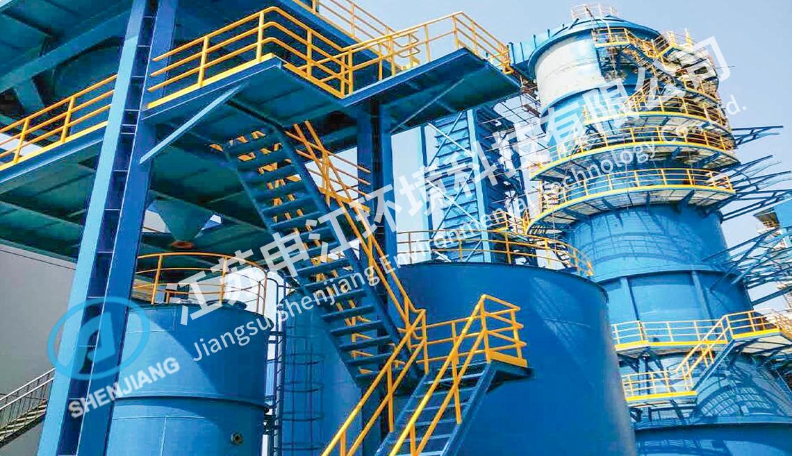 SNCR Flue Gas Denitrification for Coal-Fired BoilersA high-temperature ammonia or urea injection route for NOx control, useful when comparing removal margins and reagent performance before specifying flue gas treatment.View Product →
How the Main Routes Compare on Efficiency and Operating Cost
Removal efficiency alone rarely decides an award, because the operating bill is driven by the liquid-to-gas ratio, reagent purity and pressure drop. The chart below shows the efficiency band you should expect from each route when the system is sized properly and the reagent meets specification.
Wet limestone-gypsum
95–99%
Magnesium oxide wet
95–98%
Seawater scrubbing
90–98%
Spray dryer absorber
80–90%
Figure 1. Expected SO2 removal band by route, assuming correct sizing, reagent quality and pH control.
A plant quoting 12 L/m³ of slurry circulation is buying efficiency with electricity; a competitor at 8 L/m³ will consume less power but has a thinner margin when the inlet load rises. Compare the two offers on annual auxiliary power, limestone consumption per tonne of SO2 removed, and gypsum disposal cost, not on the tower price alone.
Materials: Where FRP Earns Its Place in the Train
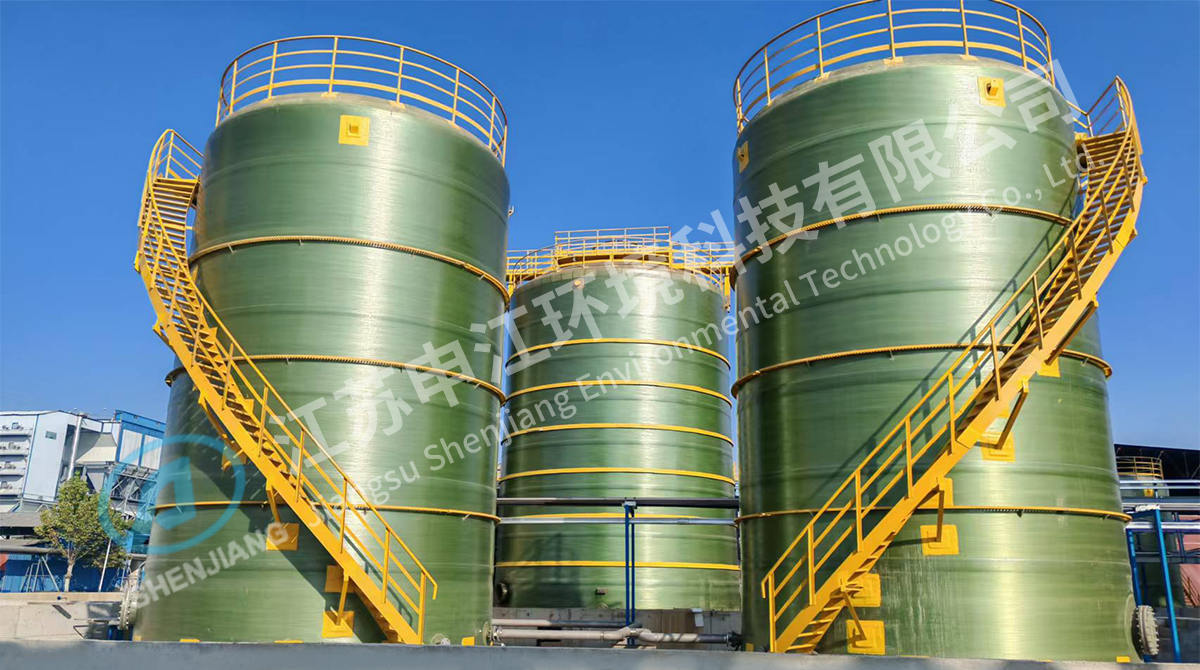
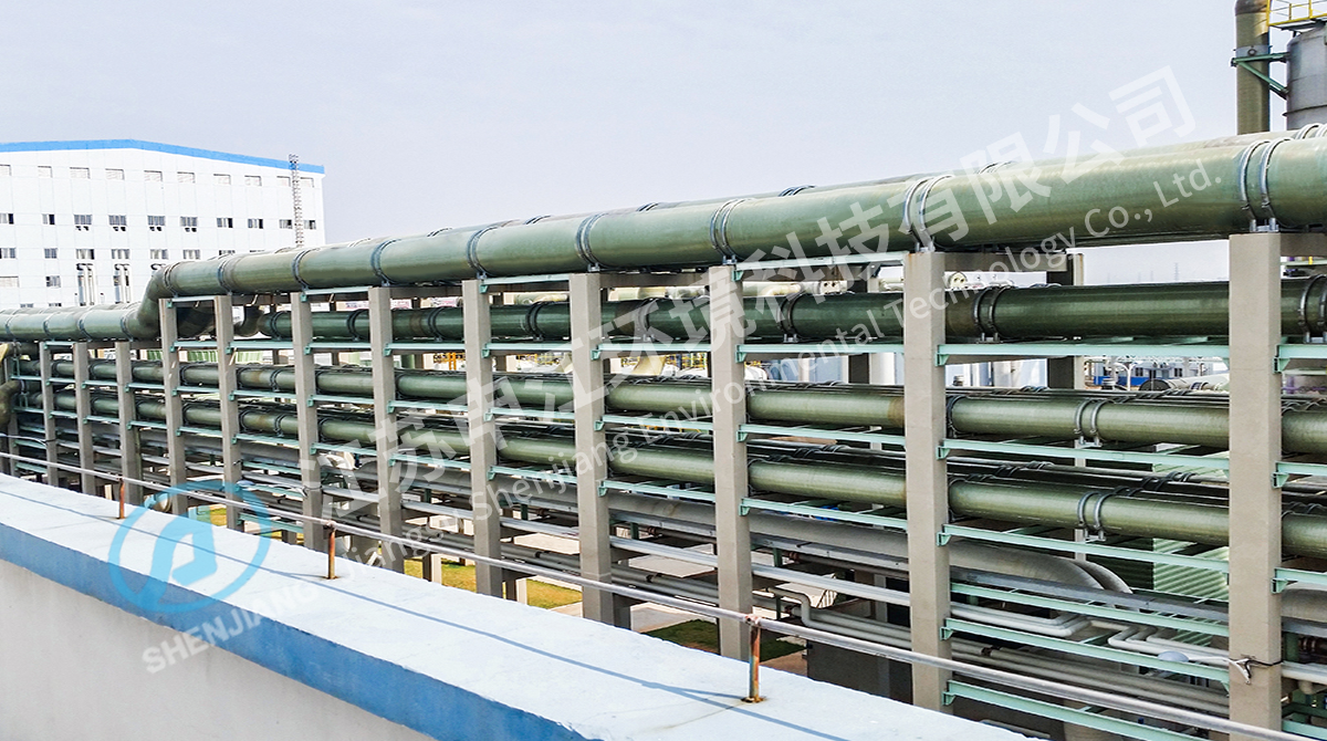
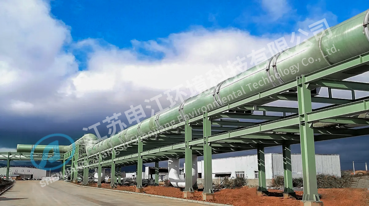
Everything downstream of the absorber outlet works in a hostile environment: 50–60 °C, pH between 2 and 5, and chloride levels that reach tens of thousands of milligrams per litre. Unlined carbon steel in that duty typically shows through-wall failures within two to three years. Fibre-reinforced plastic with a vinyl ester resin system and a resin-rich corrosion barrier of 4–5 mm, backed by a C-glass veil, holds up for a decade or more at a fraction of the weight of a rubber-lined steel alternative.
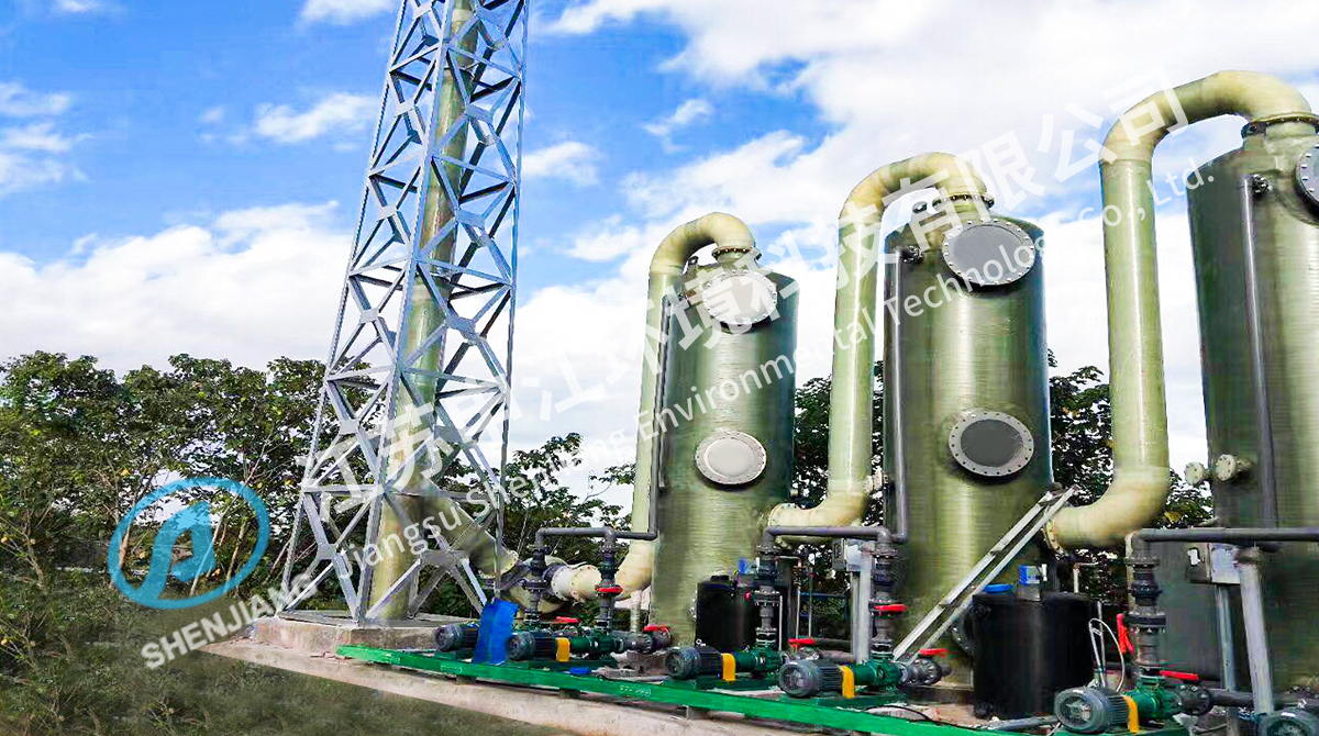
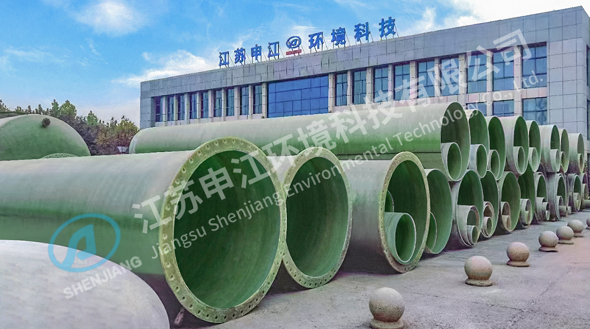
FRP also makes sense for the smaller absorption and scrubbing towers used on chemical, chemical fibre and odour-control duties, where shop fabrication keeps the delivery short and the site work limited to jointing. Jiangsu Shenjiang Environmental Technology has manufactured composite process equipment from its Yancheng base since 1996, with a 3,000 m² research centre and more than 100 production and test machines supporting both the FRP product line and complete gas treatment projects.
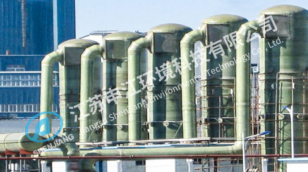 FRP Scrubbing Tower for Corrosive Waste Gas TreatmentFiberglass-reinforced plastic tower for acidic, alkaline and solvent-laden exhaust, worth reviewing where corrosion resistance and shop-fabricated delivery suit chemical or odour-control duties.View Product →
Procurement Risks and Inspection Points
The failures that hurt most are rarely the ones the datasheet covers. Build these checks into the purchase order:
- Verify the resin type and corrosion barrier thickness on a test coupon, not only on the certificate.
- Confirm pump curves at the real slurry density, typically 1.15–1.25 kg/L, rather than at water density.
- Check nozzle orientation against the actual duct routing; a 30-degree mismatch on site becomes a re-fabrication.
- Require hydro tests on towers and pipelines before shipment, with records.
- Define the performance test conditions precisely: gas flow, inlet SO2, temperature, reagent analysis and averaging period.
- Agree a recommended spare parts list at order stage, when lead times are still short.
Fitting Desulfurization Into an Ultra-Low Emission Train
Order of equipment matters. Where dust limits fall to 5 mg/Nm³ and SO3 aerosol is a visible-plume problem, a wet electrostatic precipitator placed after the absorber cleans up what the mist eliminator lets through. Where selective catalytic reduction sits upstream, part of the SO2 converts to SO3, which raises the acid dew point and pushes duct material selection toward higher-grade alloys or resin systems. Ammonia slip from the SCR also adds ammonium bisulfate deposition risk in the air preheater, so the desulfurization layout and the DeNOx layout have to be designed together, not sequentially.
Plants that have already run this integration route include several power industry projects where desulfurization, denitrification and dedusting were delivered as one coordinated system rather than three separate packages.
 SCR Flue Gas Denitrification for NOx Emission ControlAmmonia-based catalytic NOx reduction for coal-fired boilers, relevant where desulfurization, denitrification and dedusting are planned as one coordinated flue gas system.View Product →
Delivery, Erection and Handover
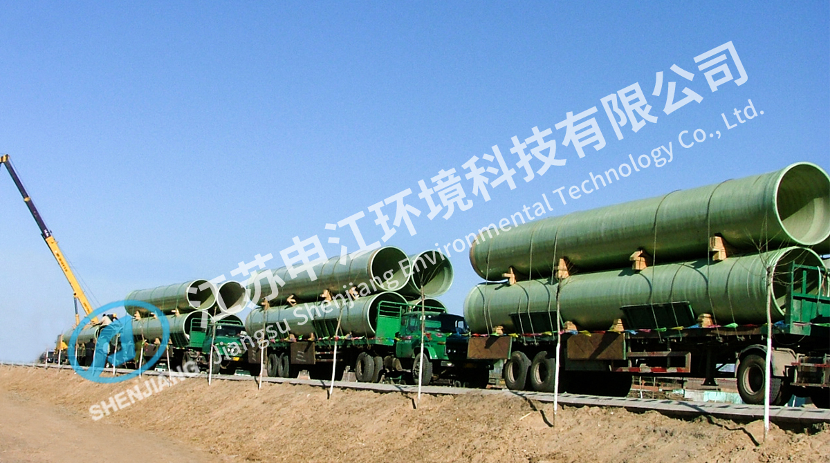
FRP components are shop-fabricated in transportable sections and jointed on site by hand lay-up, which means curing time and ambient temperature become schedule risks in winter or during the rainy season. Plan the jointing sequence so that duct spools and tower sections arrive in erection order, and keep temporary supports under long horizontal runs until the permanent hangers are set.
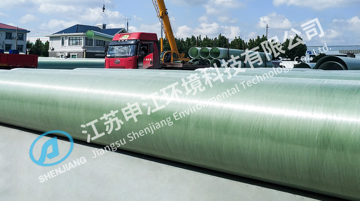
Site storage deserves equal attention. Pipe and duct sections stacked on uneven ground will ovalise under their own weight, and long unsupported spans sag before commissioning. Practical guidance on stacking heights, support spacing and UV protection is summarised in these storage precautions for desulfurization pipelines, which are worth passing to the site team before the first delivery arrives.
For a system that has to hold a guarantee for a decade, the specification work in the first two weeks matters more than the tower drawing. Fix the gas data, define the reagent and byproduct route, state the margins explicitly, and check the corrosion barrier before the equipment leaves the shop. That sequence is what separates a desulfurization train that passes its performance test on the first attempt from one that is still being adjusted the following spring.




 English
 中文简体
 Español
 عربى
 русский
 ไทย
 Indonesia
 Tiếng Việt