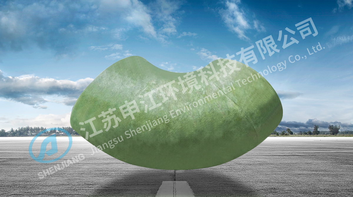
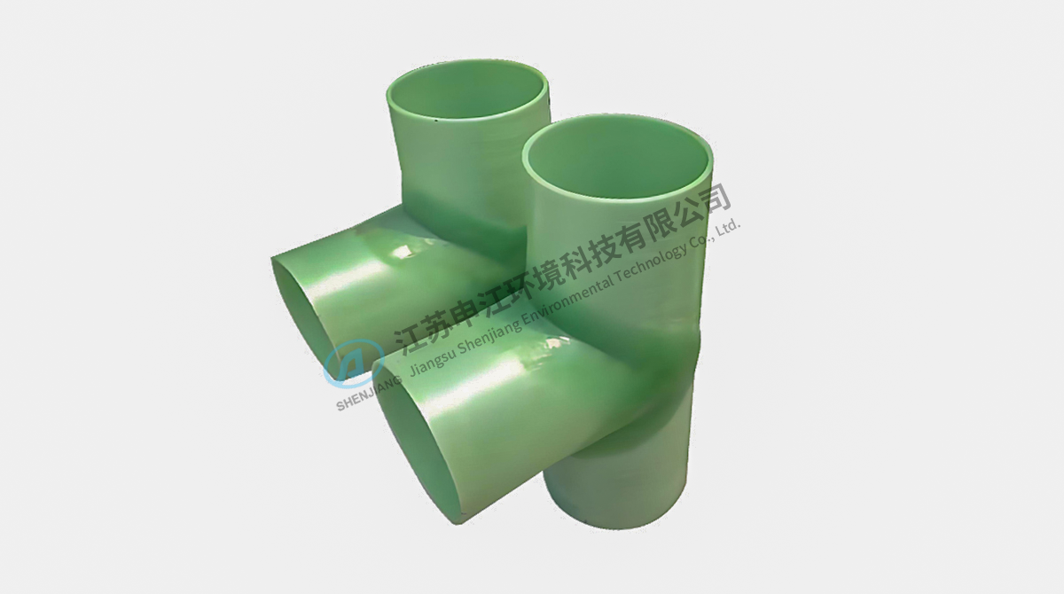
A carbon steel exhaust header in a coastal chemical fiber plant usually fails the same way. The outside still looks serviceable, the inside is a rust and salt sandwich, and the first pinhole appears three or four years after commissioning. Replacing that line with FRP pipes removes the corrosion problem outright, and it brings a different set of engineering questions. The short version: fiberglass reinforced plastic piping is the right answer for corrosive, low to medium pressure service below roughly 100 °C, and it stops being the right answer as soon as those conditions change. The pipe wall rarely fails on its own; the joint, the support spacing or the resin grade usually decides the outcome.
What FRP pipes are, in practical terms
FRP stands for fiberglass reinforced plastic. In Europe the same product is often called GRP, for glass reinforced plastic, and there is no technical difference between the two terms. Continuous glass filaments or chopped strand mat are bonded in a thermosetting resin matrix, so the finished wall is a composite: the glass carries the mechanical load, the resin carries the chemical duty.
Three manufacturing routes, three levels of consistency
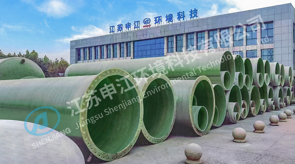
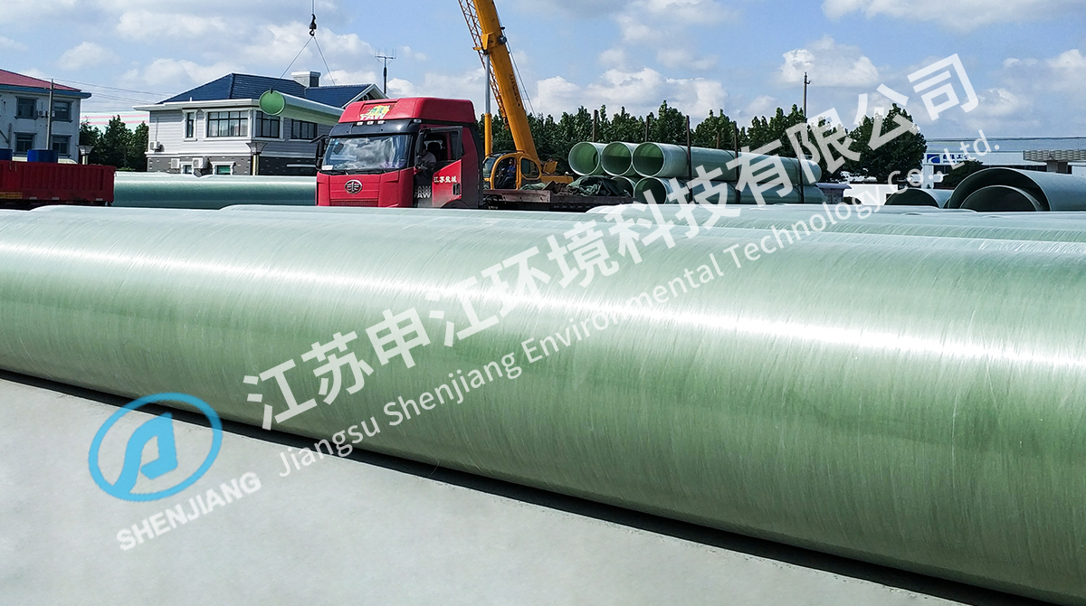
- Filament winding: glass roving is wound onto a mandrel at a controlled angle while resin is applied in the same pass. This gives the most consistent hoop strength and wall thickness and is the normal route for pressure lines and larger diameters.
- Contact molding, or hand lay-up: resin and mat are applied by hand. It suits one-off pieces, large fittings and complex shapes rather than long runs of pipe.
- Centrifugal casting: resin and glass are distributed against the inside of a rotating mould, a route common for smaller diameters and drainage products.
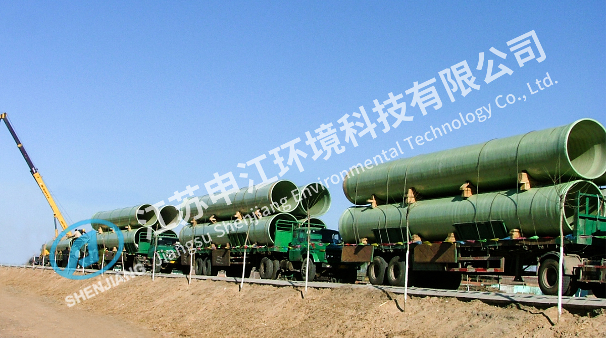
Specifiers choose the material for predictable reasons. There is no cathodic protection to maintain, no internal lining to repair, and the bore stays smooth because the wall does not scale the way steel does. Weight is roughly one quarter to one fifth of steel at the same bore, which reduces support steelwork, crane time and installation hours. Standard lengths of 6 or 12 metres also mean fewer joints per hundred metres, and every joint removed is a leak path removed. For a like-for-like view of field behaviour, our comparison of FRP pipe and steel pipe covers the service conditions where that advantage disappears.
FRP against steel, HDPE and PVC
The table below is not a ranking. Each material wins in a different part of the operating envelope, and the deciding column is usually temperature, not price.
Indicative comparison of common industrial pipe materials; exact limits depend on resin grade, wall construction and the manufacturer's data sheet.
| Material |
Density (g/cm3) |
Chemical resistance |
Continuous service temperature |
Main joining method |
Installed weight |
| FRP, vinyl ester |
1.8 to 2.0 |
Good to excellent; set by the resin |
About 90 to 110 °C |
Butt-and-strap, adhesive bell and spigot, flanged |
Low |
| Carbon steel |
7.85 |
Poor unless lined or coated |
Above 400 °C unlined |
Welded, flanged |
High |
| HDPE |
0.94 to 0.96 |
Good for many acids and alkalis |
About 60 to 80 °C |
Butt fusion, electrofusion |
Medium |
| PVC and CPVC |
1.4 to 1.55 |
Good for many acids |
Up to about 60 °C |
Solvent cement, flanged |
Low |
Density of common pipe materials (g/cm3)
Carbon steel7.85
FRP, vinyl ester2.0
PVC / CPVC1.5
HDPE0.95
Below about 60 °C and inside a modest pressure envelope, HDPE and PVC are cheaper and quicker to install than FRP. Above that temperature, or where the medium carries an oxidising agent such as chlorine dioxide or hypochlorite, the commodity plastics drop out and the choice narrows to FRP with the correct resin, or to a lined metal pipe with a maintenance routine attached to it. Density is only a proxy for handling weight, but it explains why composite lines go in so quickly: a two-person crew can often carry a 6 metre length by hand.
The specification items that decide whether the line works
Two quotations for the same nominal diameter can differ by a factor of two, and the difference is almost never the diameter. It is the wall construction, the stiffness class and the resin.
Stiffness class and pressure class are separate numbers
Pressure class, written PN 6, PN 10 or PN 16, describes internal pressure capability at a reference temperature, normally 23 °C. Stiffness class, written SN 2500, SN 5000 or SN 10000, describes resistance to ring deflection, which is the figure that matters for buried pipe. A pipe can be strong in pressure and weak in stiffness, or the reverse. Buried installations are normally designed so that long-term deflection stays under about 5 per cent of the mean diameter.
Resin grade sets the chemical ceiling
- Orthophthalic polyester: water and weak acids, lowest cost.
- Isophthalic polyester: broader acid and alkali resistance, common in industrial drainage.
- Bisphenol-A vinyl ester: strong acids, oxidising agents and chlorine-bearing streams, the usual choice for flue gas and seawater duty.
- Epoxy: higher temperature capability at a higher price.
The resin-rich inner liner with a surface veil is the part that actually touches the medium. If that liner is scratched during transport or jointing, chemical attack starts in that spot, so the liner is worth inspecting before the pipe is lifted into position.
Temperature derating is not optional
A pipe rated PN 10 at 23 °C does not hold PN 10 at 90 °C. Allowable stress falls as temperature rises, and chemical attack accelerates at the same time, which is why hot lines deserve their own calculation rather than a copy of a cold line's data sheet.
 FRP Heat-Resistant Pipe for High-Temperature Corrosive Fluid ServiceUseful where hot lines require a heat-resistant pipe grade instead of a standard winding to retain mechanical properties at working temperature.View Product →
Where the medium runs hot, for example dryer exhaust, certain scrubber circuits or condensate, a heat-resistant pipe grade is specified instead of a standard winding so the resin keeps its mechanical properties at the working temperature.
Joints and supports: where most FRP problems start
The joint is the weakest point of most composite systems and the point where quality control is thinnest. Four methods cover almost every project: butt-and-strap, where pipe ends are ground to a taper and laminated with mat and resin; bell and spigot with adhesive, fast and neat for above-ground and drainage work; flanged connections for valves, pumps and equipment; and mechanical couplings for repairs. Restrained joints carry axial thrust themselves, while unrestrained joints need anchors, guides and thrust blocks designed for the full thrust load.
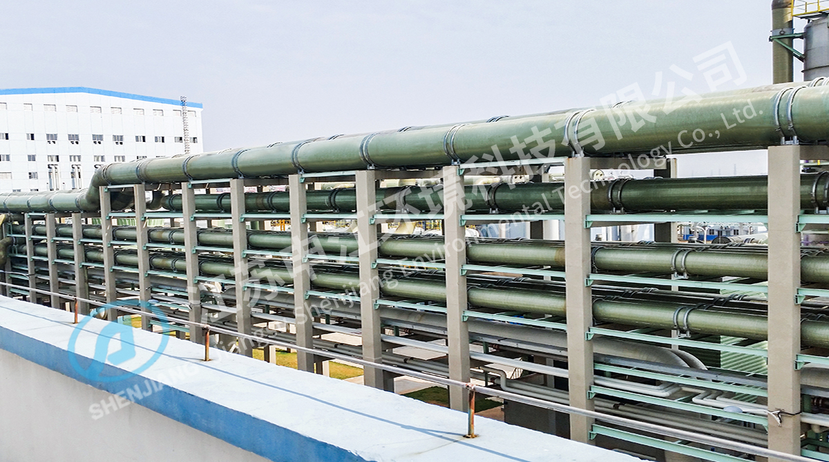
Support spacing for above-ground FRP lines typically falls between 1.5 and 3 metres for smaller diameters, tighter as temperature rises. The thermal expansion coefficient is roughly 2 to 3 times 10 to the power of minus 5 per °C, higher than steel, so long runs need expansion loops, offsets or expansion joints rather than brute-force anchoring. Common failure modes are worth naming before design starts:
- Weeping joints caused by incomplete cure, dirty surfaces or the wrong resin for the ambient temperature.
- Liner blistering where the resin-rich layer was damaged and the medium reached the structural laminate.
- UV chalking and fibre show on exposed runs that were never given a pigmented or UV-resistant topcoat.
- Over-deflection in buried pipe from poor backfill compaction or the wrong stiffness class.
- Abrasion on slurry lines, where an abrasive medium needs a different liner rather than a thicker wall.
Where FRP pipes are used
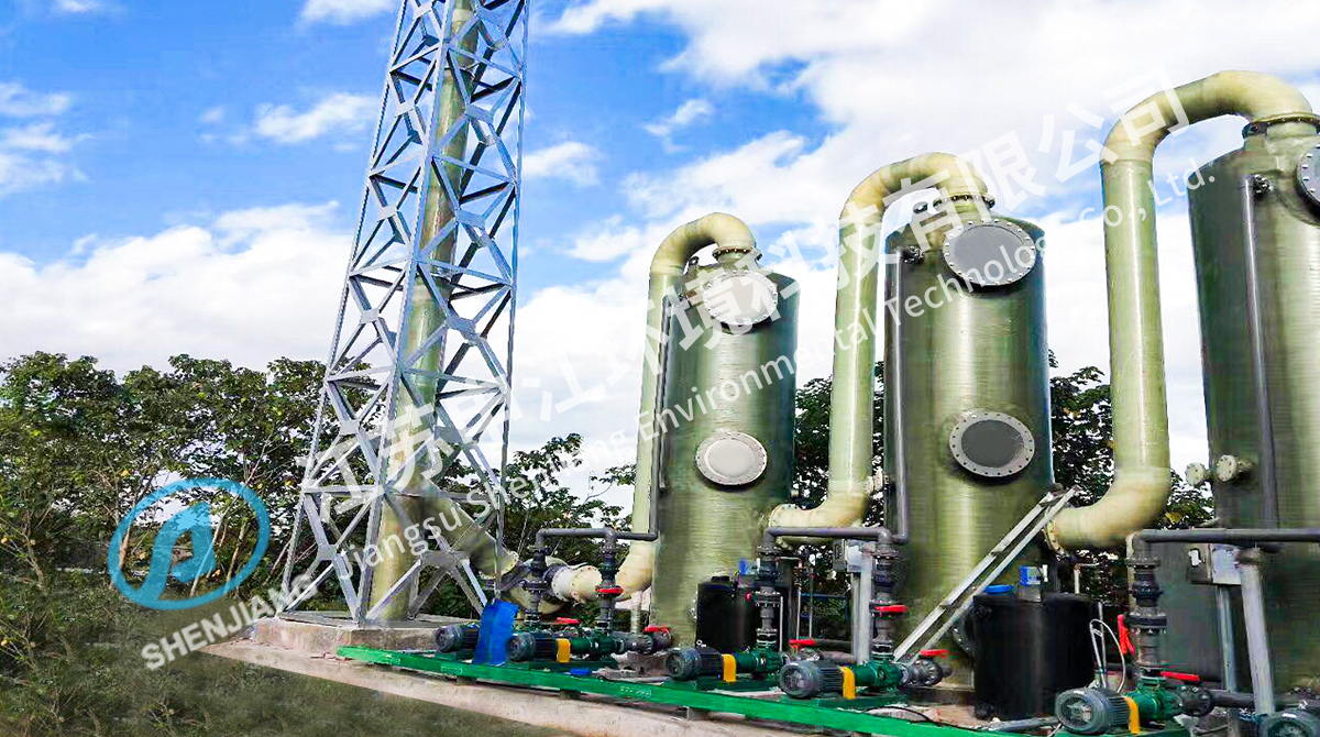
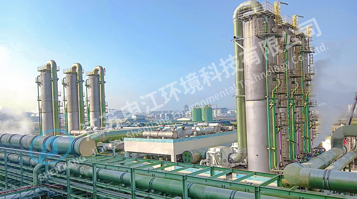
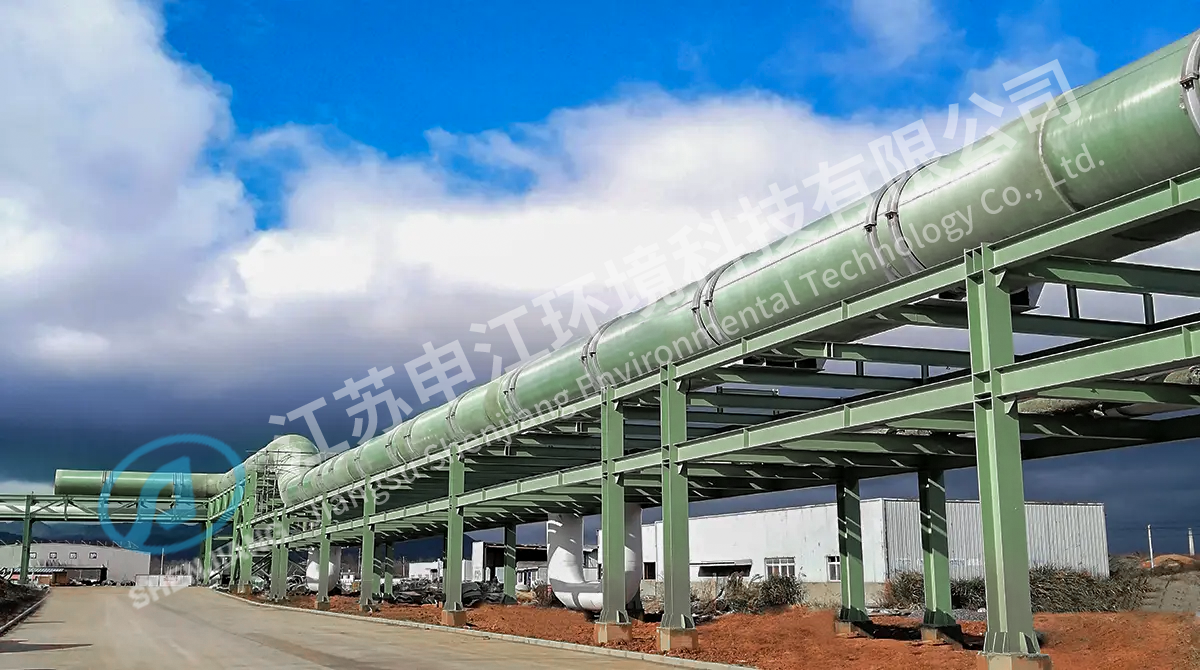
Composite piping appears wherever a metal line is being replaced for corrosion reasons rather than for pressure reasons. In chemical fiber plants it carries acid-laden and CS2-bearing exhaust; in paper mills it handles chlorine dioxide and bleach streams; in power stations it serves flue gas desulfurization absorbers and limestone slurry circuits. Oil and gas facilities use it for produced water and process water, desalination plants use it for intake and outfall lines, and general industry uses it for waste gas transportation where a duct has to survive both the chemical load and the weather.
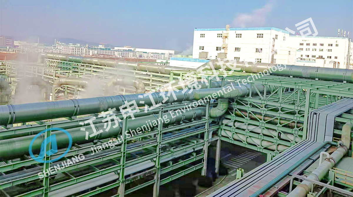 FRP Waste Gas Transportation Pipeline for Corrosive Industrial Exhaust SystemsSuited to wet, corrosive exhaust lines in chemical, pharmaceutical, and papermaking plants, offering corrosion resistance, low fluid resistance, and lightweight installation.View Product →
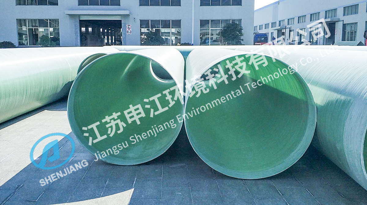 FRP Seawater Submerged Pipe for Marine and Desalination ApplicationsDesigned for submerged seawater lines exposed to chlorides, marine growth, and burial, with corrosion resistance and long-term structural integrity.View Product →
The two product families above illustrate how far the material is pushed: waste gas transport lines that run wet and corrosive for decades, and submerged seawater lines that face constant chloride exposure, marine growth and burial in the seabed.
A procurement checklist before the order is released
- State the medium, its concentration, the temperature range and any trace oxidiser, instead of writing "acid" on the enquiry.
- Fix the pressure class and the stiffness class as two separate requirements.
- Ask for the resin type, the liner construction and the glass content on the data sheet.
- Confirm the jointing method and who will laminate the joints on site.
- Request support and guide spacing drawings calculated for the actual stiffness class.
- Require a hydrostatic test at 1.5 times design pressure, plus a check on wall thickness and ovality.
- Confirm UV protection for exposed runs and the approved repair procedure for field damage.
- Order spare fittings, resin and mat with the first shipment, and check the supplier's references in your own industry.
Composite piping is not a commodity bought by diameter and price alone. The material choice is straightforward once the medium, temperature and pressure are written down honestly; the risk sits in the details that follow, which are the resin specification, the joint lamination and the support design. A supplier that manufactures the pipe and also engineers the waste gas or flue gas system around it can close that gap, because the pipe, the fittings and the support layout then come from one set of assumptions rather than three. Write the service conditions down first, and the rest of the specification tends to write itself.




 English
 中文简体
 Español
 عربى
 русский
 ไทย
 Indonesia
 Tiếng Việt